|
CDLF32 VERTICAL MULTI-STAGE CENTRIFUGL PUMPS
Application
CDL/CDLF is a kind of multifunctional products.It can be used to convey various from tap water to industrial liquid at different temperature and with different flow rate and pressure.CDL type is applicable to conveying non-corrosive liquid,while CDLF is suitable for slightly corrosive liquid.
8Water supply: Water filter and transport in Waterworks, boosting of main pipeline, boosting in high-rise buildings.
8Industrial boosting: Process flow water system, cleaning system, high-pressure washing system, fire fignting system.
8Industrial liquid conveying: Cooling and air-conditioning system, boiler water suppy and condensing system, machine-accociated purpose, acids and alkali.
8 Water treatment: Ultrafiltration system, reverse osmosis system, boiler water supply and condensing system, distillation system, separator, swimming pool.
8 Irrigation: Farmland riiigation, spray irrigation, dripping irrigation.
Operation conditions
8Thin, clean, non-flammable and non-explosive liqid containing no solid granules and fibers.
8Liquid temperature: Normal temperature type: -15℃~+70℃,Hot water type: +70℃~+120℃
8Ambient temperature: up to +40℃.
8 Altitude: up to 1000m.
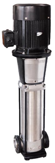
Pump
CDL/CDLF is a kind of vertical non-self priming multistage centrifugal pump,which is driven by a standard electric motor. The motor output shaft directly connects with the pump shaft through a coupling. The pressure-resistant cylinder and flow passage components are fixed between pump hesd and in-and outlet section with tie-bar bolts. The inlet and outlet are located at the pump bottom at the same plane. This kind of pump can be equipped with an intelligent protector to effectively prevent it from dry-running, out-of-phase and overload.
Electric motor
8Full-enclosed air-blast two-pole standard motor.
8Protection class: IP55
8Insulation class: F
8 Standard voltage: 50Hz: 1 x 220-230 / 240V
3 x 200-220 / 346-380V
3 x 220-240 / 380-415V
3 x 380-415V
Minimum inlet pressure NPSH
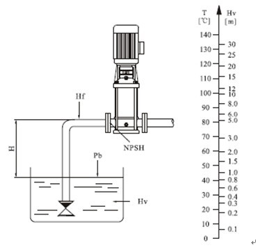
In case that the pressure in pump is lower than the steam pressure used to convey liquid, the cavitations will occur. To avoid cavitations, a minimum pressure at the inlet side of the pump shall be guaranteed. The maximum suction stroke can be calulated with following formula: H=Pb x 10.2-NPSH-Hf-Hs
Pb=atmosphere pressure [bar]
(can be set as 1bar)
In a closed system, Pb means system pressure [bar]
NPSH=Nct positive suction head [m]
(It can be read out from the point of possible max. flow rate shown on NPSH curve)
Hf=Pipeline loss at the inlet [m]
Hv= Steam pressure [m]
Hs= Safety margin=Minimum 0.5m delivery head
If the calculated result H is positive, the pump may run under the max. Suction stroke H.
In case the calculated result H is negative, a delivery head of min.Inlet pressure is necessary.
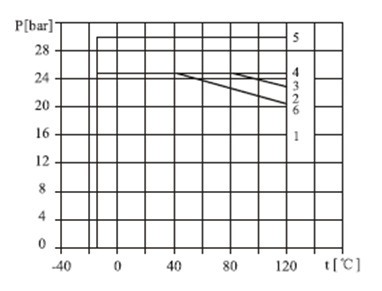
Max.Working pressure
The following figure shows the limitation of pressure and temperature, which shall be in the scope as shown in the figure.
Max.Ambient temperature
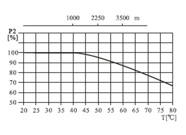
When the pump operates under ambient temperature higher than 40 ℃ or under altitude higher than 1000m, because of low air density and poor cooling effects, the motor output power P2 will be decreased to certain extent. If the pump is operated under the above-said conditions, it should be equipped with motor of higher power.
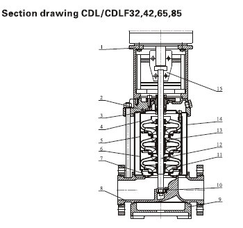
Material CDL/CDLF32,42,65,85
|
NO. |
Name |
Material |
AISI/ASTM |
|
1 |
Motor |
|
|
|
2 |
Pump head |
Cast iron |
ASTM25B |
|
4 |
Mechanical seal |
|
|
|
5 |
Top diffuser |
Stainless steel |
AISI304 |
|
6 |
Diffuser |
Stainless steel |
AISI304 |
|
7 |
Support diffuser |
Stainless steel |
AISI304 |
|
8 |
Inducer |
Stainless steel |
AISI304 |
|
11 |
Bearing |
Tungesten carbide |
|
|
12 |
Impeller |
Stainless steel |
AISI304 |
|
13 |
Shaft |
Stainless steel |
AISI304
AISI316L |
|
14 |
Impeller sleeve |
Stainless steel |
AISI304 |
|
15 |
Cylinder |
Stainless steel |
AISI304 |
|
16 |
Coupling |
Carbon steel |
|
|
CDLF |
|
3 |
Seal base |
Stainless steel |
AISI304 |
|
9 |
Inlet and outlet chamber |
Stainless steel |
AISI304 |
|
10 |
Base plate |
Cast iron |
ASTM25B |
|
CDL |
|
9 |
Inlet and outlet chamber |
Cast iron |
ASTM25B |
Product range
|
Description |
CDL1 |
CDL2 |
CDL3 |
CDL4 |
CDL8 |
CDL12 |
CDL16 |
CDL20 |
CDL32 |
CDL42 |
CDL65 |
CDL85 |
|
Rated flow[m3/h] |
1 |
2 |
3 |
4 |
8 |
12 |
16 |
20 |
32 |
42 |
65 |
85 |
|
Rated flow[l/s] |
0.28 |
0.56 |
0.83 |
1.1 |
2.2 |
3.3 |
4.4 |
5.6 |
8.9 |
11.7 |
18 |
24 |
|
Flow range[m3/h] |
0.4-2 |
1-3.5 |
1.2-4 |
1.5-7 |
5-12 |
7-16 |
8-22 |
10-28 |
16-40 |
25-55 |
30-80 |
50-110 |
|
Flow range[l/s] |
0.11-0.56 |
0.28-0.97 |
0.33-1.1 |
0.42-1.9 |
1.4-3.3 |
1.9-4.4 |
2.2-6.1 |
2.8-7.8 |
4.4-11.1 |
6.9-15.3 |
8.3-22.2 |
13.8-30.5 |
|
Max.pressure[bar] |
21 |
23 |
22 |
21 |
21 |
22 |
22 |
23 |
26 |
30 |
22 |
17 |
|
Motor power[kW] |
0.37-2.2 |
0.37-3 |
0.37-3 |
0.37-4 |
0.75-7.5 |
1.5-11 |
2.2-15 |
1.1-18.5 |
1.5-30 |
3.0-45 |
4.0-45 |
5.5-45 |
|
Temperature range[℃] |
-15~+120 |
|
Max.efficiency[%] |
44 |
46 |
54 |
57 |
62 |
63 |
66 |
69 |
73 |
75 |
76 |
77 |
|
Type |
|
CDL |
· |
· |
· |
· |
· |
· |
· |
· |
· |
· |
· |
· |
|
CDLF |
· |
· |
· |
· |
· |
· |
· |
· |
· |
· |
· |
· |
| CDL Pipe connection |
| DIN Flange |
DN25 |
DN25 |
DN25 |
DN32 |
DN40 |
DN50 |
DN50 |
DN50 |
DN65 |
DN80 |
DN100 |
DN100 |
| Oval Flange |
G1 |
G1 |
G1 |
G11/4 |
G11/2 |
|
|
|
|
|
|
|
| CDLF Pipe connection |
| Din Flange |
DN25 |
DN25 |
DN25 |
DN32 |
DN40 |
DN50 |
DN50 |
DN50 |
DN65 |
DN80 |
DN100 |
DN100 |
| Cutting ferrule joint |
· |
· |
· |
· |
· |
· |
· |
· |
|
|
|
|
| Pipe thread |
· |
· |
· |
· |
· |
· |
· |
· |
|
|
|
|
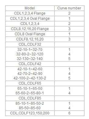
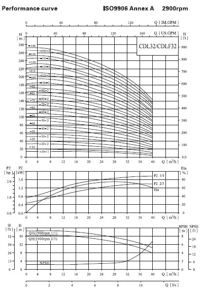
Performance curve
Following conditions are suitable for the performance curves shown bellow:
1、 All curves are based on the measured values of 50Hz;constant motor sspeed 2900rpm or 2950rpm.
2、 Curve tolerance in conformity with ISO9906 Annex A.
3、 Measurement is done with 20℃ air-free water,kinematic viscosity of 1mm2/sec.
4、 The operation of pump shall refer to the performance region indicated by the thickened curve to prevent overheating due to too small flow rate or overload of motor due to too large flow rate.
Installation sketch
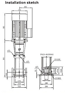
|
Pump Model |
POWER |
Q |
16 |
20 |
24 |
28 |
32 |
36 |
40 |
D
I
M
E
N
S
I
O
N
S
mm |
B1 |
B2 |
B1+B2 |
D1 |
D2 |
Weight |
|
KW |
(m3/h) |
(kg) |
|
CDL32-10-1 |
1.5 |
H
(m) |
14 |
13 |
12 |
11 |
9 |
7 |
4 |
505 |
290 |
795 |
190 |
155 |
68 |
|
CDL32-10 |
2.2 |
18 |
17 |
15 |
14 |
13 |
11 |
8 |
505 |
290 |
795 |
190 |
155 |
71 |
|
CDL32-20-2 |
3.0 |
29 |
28 |
26 |
23 |
20 |
16 |
11 |
575 |
315 |
890 |
197 |
165 |
78 |
|
CDL32-20 |
4.0 |
36 |
34 |
32 |
29 |
27 |
23 |
18 |
575 |
335 |
910 |
230 |
180 |
84 |
|
CDL32-30-2 |
5.5 |
47 |
44 |
41 |
38 |
33 |
28 |
21 |
645 |
430 |
1075 |
260 |
208 |
93 |
|
CDL32-30 |
5.5 |
54 |
51 |
48 |
44 |
40 |
35 |
27 |
645 |
430 |
1075 |
260 |
208 |
93 |
|
CDL32-40-2 |
7.5 |
65 |
62 |
58 |
53 |
46 |
40 |
30 |
715 |
490 |
1145 |
260 |
208 |
102 |
|
CDL32-40 |
7.5 |
72 |
69 |
65 |
59 |
53 |
47 |
37 |
715 |
490 |
1145 |
260 |
208 |
102 |
|
CDL32-50-2 |
11 |
83 |
79 |
74 |
68 |
60 |
52 |
41 |
890 |
490 |
1380 |
330 |
255 |
172 |
|
CDL32-50 |
11 |
90 |
86 |
81 |
74 |
67 |
59 |
47 |
890 |
490 |
1380 |
330 |
255 |
172 |
|
CDL32-60-2 |
11 |
101 |
97 |
90 |
83 |
74 |
65 |
51 |
960 |
490 |
1450 |
330 |
255 |
176 |
|
CDL32-60 |
11 |
108 |
104 |
97 |
90 |
81 |
72 |
57 |
960 |
490 |
1450 |
330 |
255 |
176 |
|
CDL32-70-2 |
15 |
119 |
114 |
107 |
98 |
88 |
78 |
60 |
1030 |
490 |
1520 |
330 |
255 |
188 |
|
CDL32-70 |
15 |
126 |
121 |
113 |
105 |
95 |
85 |
67 |
1030 |
490 |
1520 |
330 |
255 |
188 |
|
CDL32-80-2 |
15 |
136 |
131 |
123 |
114 |
102 |
90 |
71 |
1100 |
490 |
1590 |
330 |
255 |
192 |
|
CDL32-80 |
15 |
144 |
138 |
130 |
120 |
109 |
97 |
77 |
1100 |
490 |
1590 |
330 |
255 |
192 |
|
CDL32-90-2 |
18.5 |
154 |
148 |
140 |
129 |
117 |
102 |
82 |
1170 |
550 |
1720 |
330 |
255 |
218 |
|
CDL32-90 |
18.5 |
162 |
156 |
147 |
136 |
124 |
109 |
88 |
1170 |
550 |
1720 |
330 |
255 |
218 |
|
CDL32-100-2 |
18.5 |
175 |
166 |
157 |
146 |
131 |
115 |
91 |
1240 |
550 |
1790 |
330 |
285 |
222 |
|
CDL32-100 |
18.5 |
182 |
173 |
164 |
152 |
138 |
122 |
98 |
1240 |
550 |
1790 |
330 |
285 |
222 |
|
CDL32-110-2 |
22 |
193 |
184 |
173 |
164 |
146 |
128 |
102 |
1310 |
590 |
1900 |
360 |
285 |
259 |
|
CDL32-110 |
22 |
200 |
191 |
180 |
168 |
153 |
135 |
109 |
1310 |
590 |
1900 |
360 |
285 |
259 |
|
CDL32-120-2 |
22 |
211 |
201 |
189 |
178 |
160 |
140 |
113 |
1380 |
590 |
1970 |
360 |
285 |
263 |
|
CDL32-120 |
22 |
218 |
208 |
196 |
184 |
167 |
147 |
120 |
1380 |
590 |
1970 |
360 |
285 |
263 |
|
CDL32-130-2 |
30 |
230 |
218 |
206 |
193 |
174 |
153 |
124 |
1450 |
660 |
2110 |
400 |
310 |
327 |
|
CDL32-130 |
30 |
237 |
225 |
213 |
200 |
181 |
160 |
131 |
1450 |
660 |
2110 |
400 |
310 |
327 |
|
CDL32-140-2 |
30 |
247 |
235 |
222 |
210 |
189 |
165 |
135 |
1520 |
660 |
2180 |
400 |
310 |
331 |
|
CDL32-140 |
30 |
255 |
242 |
229 |
216 |
196 |
172 |
142 |
1520 |
660 |
2180 |
400 |
310 |
331 |
|